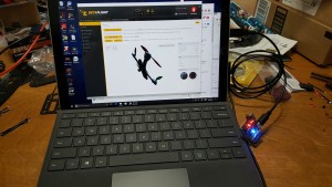
Ok, so the first time anything had any power through it. I installed the betaflight software on my laptop, and connected the flight controller to the laptop. Things worked pretty well and the flight controller was recognized. I then went ahead and flashed the update to the controller so that it was at the current version of betaflight. Maybe I’m easily amused, but I did find it kinda neat that on the page being shown, as I’d move the flight controller around, the image of the quad copter would also move in unison with the flight controller. At least that means that the various sensors appear to all be working.
quad copter build
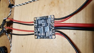
Battery wires to the power distribution board
Attach esc’s to the power distribution board
Shortening motor and esc wires
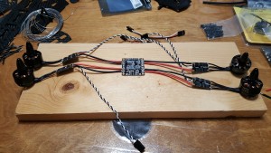
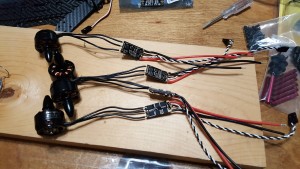
After initially thinking that I’d leave all the wires at their original length, after I started comparing how things would fit onto the frame and how long all the excess wires would be I realized that it wasn’t going to be practical, so I shortened the wires from the motor to the esc and then from the esc to the power distribution board to something that would more reasonably work.
Power distribution board
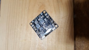
Flight controller
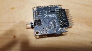
I went with an X-Racer F303 v3.1 flight controller. Pretty basic controller for doing things like building a racing quad. This controller lacks the ability to do things like gps, but for a racing quad that’s not needed.
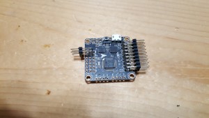
The controller comes without the pin headers installed, so the first step was to install those.
Lots of little tiny spots to solder. I had to get a small tip for my soldering iron in order to do this, because all I had was about a quarter inch chisel tip style tip. I actually put more headers in than I really needed. On the left side I really only need the 1 for the sbus connection, but I thought 2 might be a little more stable. On the right, I only really need channels 1-4, plus a channel for bringing in power, and the led pin set. I figured it was easier just to put all of them in over there.
I did have a moment of panic while I was testing things with the multimeter to make sure I didn’t short circuit everything. I was testing between various pins and getting continuity between them. Took me a minute or so to figure out that that made sense – pins all along the ground line naturally all are connected to each other.
Motors and ESCs
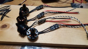
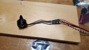
First step is soldering the motors to the ESC. For this build, I went with SunnySky 2100Kv X2207S motors and ZTW 20A escs. The motor wires solder onto pads directly on the esc. When I started this, my original plan was to leave the wires the original length and just tuck them in under the parts as I assembled. So what you see here is the wires left at their original length.
Then after the first motor, the other 3 motors also need soldered.
Beginning quad copter build
I’ve been pondering for a while building an fpv racing style quad copter. Flying around just taking photos with a quad just never really quite interested me, but the more I watched video of the fpv racing stuff, the more that seemed like something I could find interesting.
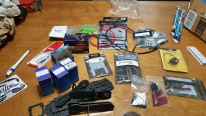
So, given that, I’ve gathered the various parts needed to build my own 250 sized quad copter. Pictured is pretty much the entire collection of stuff except for the video goggles.
